Servo Motor Control
In this project, we build a Toll Barrier by using a servo motor. When we click a push button, the servo motor will rotate and a green LED will glow indicating the driver to move ahead.
Circuit

Components
- 1 Smowboard Think Mini
- 1 Servo Motor
- 1 green LED
- 1 100 ohm resistor
- 1 push button
- 2 male-to-male jumper wires
- 5 male-to-female jumper wires
In this circuit, we use a servo motor to create a toll barrier. The servo motor is grounded by connecting one of its pin to the ground of Smowboard. A power supply is given to the motor by connecting one pin to the Vin pin of Smowboard. The third pin of the servo motor is connected to the pin number 2 of Smowboard. The Smowboard controls the motor with this pin. The LED is grounded by connecting its cathode to the ground of Smowboard. To limit the flow of current a 100 ohm resistor is connected in series with the cathode side. The anode of LED is connected to the pin number 4 of the Smowboard. We use a push button. The servo motor will operate when this button is clicked. The push button is grounded by connecting one of its pins to the ground of Smowboard. The other pin is connected to the pin number 23 of Smowboard.
The servo motor is connected to the Smowboard. Smowboard smartly controls the rotation of the motor. Thus, when the push button is clicked, the motor rotates by an angle of 90 degrees. The Smowboard also controls the voltage across the LED which is connected. When the push button is clicked, a voltage is applied across the LED. A current flows across the LED due to this voltage and the LED glows indicating the driver a GO signal.
Flow
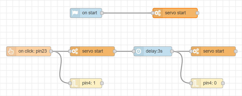
[{"id":"18432e1e.7b3442","type":"tab","label":"Flow 1","disabled":false,"info":""},{"id":"3327f83f.bf9368","type":"common/on start","z":"18432e1e.7b3442","config_props":{"name":""},"outputProps":{},"dependency_set":{},"x":250,"y":140,"wires":[["c7460e4a.fd782"]]},{"id":"c7460e4a.fd782","type":"smow_motor/servo","z":"18432e1e.7b3442","config_props":{"name":"","motor":"81832484.6c1ff8","angle":"0"},"outputProps":{},"dependency_set":{},"x":460,"y":140,"wires":[[]]},{"id":"b7acb956.1a2ae8","type":"smow_pin/on button click","z":"18432e1e.7b3442","config_props":{"name":"","pin_number":"23","connection_type":"0","auto_pull_up_down":"true"},"outputProps":{},"dependency_set":{},"x":230,"y":240,"wires":[["ff6a0c1b.c9ad8","c33fdbbc.a870a8"]]},{"id":"4d8ad740.9af9b8","type":"smow_motor/servo","z":"18432e1e.7b3442","config_props":{"name":"","motor":"81832484.6c1ff8","angle":"90"},"outputProps":{},"dependency_set":{},"x":450,"y":240,"wires":[[]]},{"id":"ff6a0c1b.c9ad8","type":"smow_motor/servo","z":"18432e1e.7b3442","config_props":{"name":"","motor":"81832484.6c1ff8","angle":"0"},"outputProps":{},"dependency_set":{},"x":850,"y":240,"wires":[[]]},{"id":"f1419087.50e44","type":"common/delay","z":"18432e1e.7b3442","config_props":{"name":"","period":"3"},"outputProps":{},"dependency_set":{},"x":660,"y":240,"wires":[["3c14c827.851ed8"]]},{"id":"c33fdbbc.a870a8","type":"smow_pin/write","z":"18432e1e.7b3442","config_props":{"name":"","pin_number":"4","level":"1"},"outputProps":{},"dependency_set":{},"x":430,"y":340,"wires":[[]]},{"id":"3c14c827.851ed8","type":"smow_pin/write","z":"18432e1e.7b3442","config_props":{"name":"","pin_number":"4","level":"0"},"outputProps":{},"dependency_set":{},"x":830,"y":340,"wires":[[]]},{"id":"81832484.6c1ff8","type":"smow_motor/servo port","z":"","config_props":{"name":"","pin":"2","motor_model":"0","submodule":"0","unit":"0","timer":"0","min_pulsewidth":"550","max_pulsewidth":"2500","frequency":"50","max_angle":"180"},"outputProps":{},"dependency_set":{"servo_sg90":true,"false_dep":false}}]
To import this code to the Studio, copy it and paste it into the import nodes dialog box in the import section.
Lets understand the code,
- The flow starts with an
on button clicknode. This node gets triggered when a button is clicked. - Double click on the node to change its properties.
- We set the 'pin no.' property as 23 as we have connected one push button to the pin number 23 of Smowboard.
- We connect the
servonode to control the servo motor. We Configure the node by clicking on the pencil icon on the 'Servo Motor' property of the node. Set the 'outpin pin' to 2 as we have connected the servo motor to pin number 2 of the Smowboard. - We then click on
Addanddoneto complete the configuration. - We set the 'Angle' property of the node to 90. This will rotate the toll barrier by 90 degrees
- We connect a
pin writenode to theon button clicknode to glow the LED when button is clicked. We set the 'pin number' as 4 and 'pin value' as 1 for thepin writenode. - Then, we connect a
delaynode to theservonode to add a delay of 3 seconds before the next node,servoruns. - This delay keeps the barrier open (i.e at an angle of 90 degrees) for 3 seconds for vehicles to pass by.
- We use another
servonode to and set its 'Angle' property to 0. This will rotate the barrier and bring it back to an angle of 0 degree. - We connect a
pin writenode to the delay node to turn OFF the LED after 3 seconds. We set the 'pin number' as 4 and 'pin value' as 0. - At the beginning, the barrier must be at 0 degree initially. For this, we add an
on startnode and connect aservonode to it. We set the 'Angle' property of the node to 0. This will keep the barrier horizontal (i.e at 0 degree) initially. - Now, we upload the code to the Smowboard using the
uploadbutton on the Studio. - We can see that when we click the push button the green LED glows and the barrier rotates by 90 degree for the vehicles to pass. It remains at 90 degree for 3 seconds and again comes back to the initial position while the LED is turned OFF.
Output

Modifications for: IR sensor based closing!
We'll now make the project intelligent by the addition of an IR sensor. The new sensor will detect if the vehicle has passed the toll barrier and we will close the barrier automatically. This will help the barrier to not close simply based on time, but rather take feedback of the IR sensor for confirmation of no vehicle being present.
Circuit

Additional Components
- 1 I-R Sensor Module
- 1 male-to-female jumper wires
- 2 female-to-female jumper wires
In the modified circuit, we have added the IR sensor to detect presence of a vehicle. We will place the IR sensor right before the toll Barrier to get correct status of the presence of the vehicle. The IR sensor has 3 pins. We will connect its Vcc pin to 3.3V of the Smowboard, its Signal pin to pin 5 of the Smowboard and its GND pin to the negative rail of the breadboard.
Flow
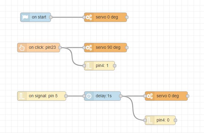
[{"type":"system","config_props":{"global_vars":[]}},{"id":"2f296d7f.cd1c92","type":"smow_pin/on signal","z":"9a76687.f6c3b98","config_props":{"name":"on signal: pin 5","pin_number":"5","event_type":"0","pullup_enable":"false","pulldown_enable":"false"},"outputProps":{},"outputs":[{"variables":[{"name":"pin level","value":"pin_level"}]}],"dependency_set":{},"x":140,"y":320,"wires":[["ccc84793.a88538"]]},{"id":"dbec663c.f91318","type":"smow_motor/servo","z":"9a76687.f6c3b98","config_props":{"name":"servo 0 deg","motor":"14a6c0a6.db888f","angle":"0"},"outputProps":{},"dependency_set":{},"x":550,"y":320,"wires":[[]]},{"id":"3b667c6a.e432a4","type":"smow_pin/on button click","z":"9a76687.f6c3b98","config_props":{"name":"","pin_number":"23","connection_type":"0","auto_pull_up_down":"true"},"outputProps":{},"dependency_set":{},"x":130,"y":160,"wires":[["3747585b.4a1f38","9f66b07c.3fd89"]]},{"id":"3747585b.4a1f38","type":"smow_motor/servo","z":"9a76687.f6c3b98","config_props":{"name":"servo 90 deg","motor":"14a6c0a6.db888f","angle":"90"},"outputProps":{},"dependency_set":{},"x":350,"y":160,"wires":[[]]},{"id":"ccc84793.a88538","type":"common/delay","z":"9a76687.f6c3b98","config_props":{"name":"","period":"1"},"outputProps":{},"dependency_set":{},"x":340,"y":320,"wires":[["dbec663c.f91318","d5c52bc7.7c7e28"]]},{"id":"9f66b07c.3fd89","type":"smow_pin/write","z":"9a76687.f6c3b98","config_props":{"name":"","pin_number":"4","level":"1"},"outputProps":{},"dependency_set":{},"x":330,"y":220,"wires":[[]]},{"id":"d5c52bc7.7c7e28","type":"smow_pin/write","z":"9a76687.f6c3b98","config_props":{"name":"","pin_number":"4","level":"0"},"outputProps":{},"dependency_set":{},"x":530,"y":400,"wires":[[]]},{"id":"b328a297.be907","type":"common/on start","z":"9a76687.f6c3b98","config_props":{"name":""},"outputProps":{},"dependency_set":{},"x":120,"y":60,"wires":[["c2dcc9a8.836808"]]},{"id":"c2dcc9a8.836808","type":"smow_motor/servo","z":"9a76687.f6c3b98","config_props":{"name":"servo 0 deg","motor":"14a6c0a6.db888f","angle":"0"},"outputProps":{},"dependency_set":{},"x":350,"y":60,"wires":[[]]},{"id":"14a6c0a6.db888f","type":"smow_motor/servo port","z":"","config_props":{"name":"","pin":"2","motor_model":"0","submodule":"0","unit":"0","timer":"0","min_pulsewidth":"550","max_pulsewidth":"2500","frequency":"50","max_angle":"180"},"outputProps":{},"dependency_set":{"servo_sg90":true,"false_dep":false}}]
To import this code to the Studio, copy it and paste it into the import nodes dialog box in the import section.
Lets understand the modifications in the code,
- The
on startandon button clickflows remain the same with a slight change. The closing of the barrier is now based on IR sensor's signal and not time based. - We use an
on signalnode for the IR sensor detection and set its 'pin number' to 5 and 'edge type' to 'positive edge (0 to 1)' because we want the barrier to close when the vehicle moves from detected to non-detected state. - After detection of the signal by the
on signalnode, we close the barrier using theservonode and turn off the LED using thepin writenode. - Now the barrier will open on click of the button and close automatically when the vehicle has moved out through the toll barrier.
Learn Coding and Electronics easily using Smowcode.